
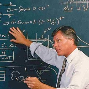
Theorist, founder of Sierra Instruments
Dr. John Olin founded Sierra Instruments in the early 1970s. He recounts the story of the early days of Sierra in the following interview Jesse Yoder conducted in November 2003 onsite at Sierra Instruments in Monterey, California.
Sierra Instruments was acquired by TASI Group on May 2, 2019, and has since integrated its flow business into the TASI Flow segment.
We recommend visiting Founder’s Archive: John G. Olin, PhD on Sierra’s website to read Dr. Olin’s fascinating white papers on thermal flowmeters and other topics. To read about John’s son Matt Olin, who served as Sierra’s president from 2003-2020, please visit our Movers and Shakers of Flow page .
Part One: How it all began
Jesse Yoder (JY): Basically what I’m doing is a series of interviews with founders of flowmeter technology. I’m trying to understand the creative process and understand how you came about this invention and understand the history of the company. What I eventually want to do is turn this into a book on flow, the history of flow, or thermal flowmeters. For now I want to learn the history of thermal technology and your company.
John Olin (JO): As I take it, you want to know the history of the innovative process. I have sketched this out, and in retrospect it is kind of interesting, I think. I enjoyed reading what FCI did. I can also talk to you about the theory of thermal mass flow meters. OK, so you want me to start with the history. I’ll talk about aspects of the theory during the history and also explain what the terms mean. I was born and raised in Chicago. I was born in 1939. I’m an only child, and I went to a regional engineering school, Illinois Institute of Technology. I could have gone to other schools, but my mother wanted me to stay local; so I did. I went to Illinois Tech and got a great education there in the mechanical engineering dept. I was captain of the basketball team, got good grades, and was a very active athlete. Because I got good grades, the chairman of the dept., Prof. Andrew Fejer, along with Prof. Jim Miller, agreed to take me on, and I did an undergraduate thesis. I was one of the few people who did an undergraduate thesis. Now they’re starting to do this more; Stanford is introducing that now. I was involved with fluid mechanics. I was in the basement of Machinery Hall, and old brownstone building, and my Dad was down there helping me take data. It was about the use of inlet turbulence to improve the efficiency of axial flow air compressors.
JY: Wait, say that again.
JO: It was how to increase turbulence in the inlet of an axial flow compressor, thereby improving its efficiency.
JY: Please explain the word axial.
JO: Axial compressors have blades like a typical propeller you’d see on an airplane or like a fan in the home, in contrast to centrifugal flow where the flow comes in the middle, and the mass of the gas or liquid gets thrown to the outside by centrifugal force. I used Pitot tubes and measured differential pressure. These experiments really got me interested in fluid mechanics. Jim Miller had gone to Stanford. There was a scholarship called the Hughes Doctoral Fellowship. At that time, it was the best doctoral fellowship in the country in terms of the amount of money you got; it was incredible. It was only good at West Coast schools, and the idea was that you might work at the Hughes Aircraft Company in the L. A. area when you graduated. So, that’s why I went to Stanford. The Hughes Fellowship paid for my graduate school – masters and doctorate. I majored in fluid mechanics and heat transfer, the pillars of mass flow meter technology and the pillars of thermal mass flow meters. My PhD thesis was entitled “Turbulence Suppression in Magnetohydrodynamic (MHD) Power Generators.” My thesis advisor was Prof. Charles Kruger, who ultimately became the M.E. Dept. Head and then V.P. of Research for Stanford. So, my graduate research was involved with a new way to generate electricity called MHD. We thought this would revolutionize the world; in the end it did not. It was a rocket engine shooting an electrically conducting gas through a channel surrounded by a superconducting magnetic field which created electricity. It never really panned out, but it was a great field for learning physics and fluid mechanics. At that time, the instrument I used was made by Thermo Systems, Inc. (now TSI) – in Minnesota. They were one of two companies in the world that manufactured hot-wire anemometers – thermal anemometers used for fluid mechanics research. The other company at that time was called Disa, a Danish company; they were later acquired by Dantec. A hot-wire anemometer is a research tool, and it is a thermal mass flow meter. Its sensor usually is a tungsten wire a fraction of a thousandth of an inch in diameter and is very fragile. It can get into small places. It is so small and fast in response that it can measure turbulence; so, turbulence research was normally done that way. Since I used an MHD power generator, which ran at about 2500 degrees C, it could melt any metal, and I had to have a cooled film anemometer. TSI made these. The thermalanemometer sensor was a six thousandth of an inch diameter cooled tube. It had a heated platinum film on the outside of it, manufactured via vacuum deposited film technology that TSI had perfected. It had high pressure water cooling the inside of it, and it could withstand these incredible temperatures. The probe itself also was water cooled, with high pressure water and a high pressure pump pumping the water through it. We were interested in the fact that when you have a flow like that, it’s highly turbulent. When you turn on the magnetic field…
JY Was this air flow?
JO: We were burning ethanol, which is in the alcohol you drink, and pure oxygen. The ethanol smelled like pure vodka. So it was rocket science, and measuring anything in this extremely hot MHD channel was very difficult. The idea was that when you turned on the magnetic field, eddy currents would be created by the conductive gas moving in the turbulent eddies, and the magnetic field would suppress that turbulent motion. Resulting magnetic induced forces always go in the direction of slowing down fluid motion. So, I was looking at how much that magnetic field can turn that turbulent flow into a more laminar flow. That was my thesis, and that’s what I did.
JY: Why do you want to suppress the turbulence?
JO: Turbulence suppression had the potential of improving the efficiency of MHD power generators by reducing their pressure drop and wall heat loss.. Here I was doing this fluid mechanics experiment. I had the pumps turned on; the fuse blew due to the excessive amount of current; the pumps turned off; I pulled out the probe; and it was fried. It was nothing but a charred mass. This was a setback, but we went to a pitot tube instead and used that to measure the turbulence. I used a pitot tube to measure the velocity profiles, and we showed that indeed the turbulent flow laminarized itself and became more laminar in nature.
JY: The turbulence is just in a gas, right?
JO: When you have a rocket engine, you have a big combustor and it’s swirling and it’s extremely turbulent.
JY: It’s a rocket engine, so it’s very hot.
JO: It’s 2500 degrees C, hot enough to melt most materials. We lined the channel with ceramic bricks.
JO: Magnetic flowmeters are based on the same principle of operation as what we were using. They are generators of electricity, but they’re cold. We did the same thing hot. We generated an electric field and this generated a current flowing through a load. That’s what magneto-hydrodynamic power generation is – exactly the same as a magnetic flow meter – except that the magnetic flow meter operates at open circuit. The open-circuit voltage increases linearly proportional to volumetric flow rate. I used the pitot tube to finish up that work. I graduated; it took a year to do my masters and four years to do my PhD in mechanical engineering. I entered in 1961 and graduated in 1966. My first jobwas at Avco Everett Research Laboratory in Boston. That’s the same company that developed the heat shields for reentry vehicles used for intercontinental ballistic missiles. The funding was from ARPA, a branch of the Air Force. Instead of being inducted into the Viet Nam War, I got an S2 deferment. The Air Force opted to have me develop weapons systems, instead of being a gun-carrying grunt in Viet Nam. The project I was on was research – not directly applicable to weapons systems. I used a plasma arc engine. Instead of heat generated by combustion by burning alcohol and oxygen, we put a megawatt of current across these copper electrodes and shot it thru the gas to heat it up. This was another way to generate electrical power via MHD. You need a hot flowing gas seeded with a material that liberates free electrons to make it electrically conductive, and you put a magnetic field across it. You have a moving conductive gas instead of moving conductive copper wires, as used in conventional electrical generators in power plants.
JY: You have a hot gas, you seed it with electrons, and then what happens?
JO: You seed it with electrons, you run it thru a channel, you have the magnetic field going across the channel. Perpendicular to that, you have electrodes. Based on Faraday’s Law, what you get is a voltage across the electrodes that runs thru a load, and now you’ve generated electricity. We used liquid cesium to seed the gas. The cesium would evaporate and create free electrons. At Stanford, we used liquid NAK, a mixture of sodium and potassium. We pushed that in with a pump; it vaporized and created the free electrons necessary to create the conductor that cuts across the magnetic field lines. NAK is a liquid. At Stanford, when we had too much of it, we would hose it down with water in the courtyard of the old Foundry Building which housed our lab. The explosive reaction between water and liquid sodium and potassium created a black cloud floating over the university. In those days, you could get away with that. That’s what I did at AVCO. It did not involve thermal anemometers at that point. Then ARPA money ran out; I was the last one hired; and I got laid off.
JY: How did that make you feel?
JO: It brought me down to earth. My wife and I were living in Boston, and I had to support my wife. So, I thought I’d check with several companies. I remembered TSI, so I interviewed them. I got the job as director of research. TSI was started by Dr. Mike Fingersen, who was a brilliant researcher who did his thesis on the cooled film anemometer that I used at Stanford. So, I learned about thermal mass flowmeters from him. At that time, I believe there was also a company in Massachusetts that made hot wire anemometers called Flow Research. TSI was number one in the world. They had hundreds of different kinds of probes with tungsten and also the hot-film sensors. In this case, the hot-film sensor was not tubular, but was a six thousandth of an inch diameter quartz rod with a platinum film around it. That film conducted electricity and self heated so it could become an anemometer. They still make that sensor to this day. The word “anemometer” comes from the Greek word “anemos”, which means “wind.” So, the word anemometer means an instrument to measure, or meter, the wind – or, now, to measure the velocity of a flowing fluid. There was a whole class of instruments at that time called air velocity meters – usually portable instruments, lower in cost, usually $300 – $400 at that time. The main application was air flow measurement in heating, ventilation, and air-conditioning (HVAC). This type of instrument turned out to be one of the first products of Sierra Instruments, Inc. There was a company called Anemotherm that made a thermal air velocity meter using a heated thermistor. The biggest company was Alnor Instruments in Chicago. In their meter, the air flow would come thru a tube which deflected a little vane, and that vane on a velocity scale was your meter. This was based on differential pressure, not thermal technology. The name “Alnor” came from the founder’s two sons’ names, Albert and Norbert. Subsequently, TSI acquired them. My research at TSI was involved with thermal mass flowmeters. At that time, when the newly introduced Boeing 747 aircraft landed, many small aircraft landing behind it crashed. This was a big disaster. It was caused by wing tip vortices. The strength of the vortices are proportional to the weight of the plane, exceptionally high for a 747. When you have airfoils, there’s an outward flow across the tip which rolls up into two opposing vortices coming off the wing tips. Everyone wanted to measure this air flow. The Air Force and the FAA were involved. So, for this application, I invented a split film sensor, a 3- dimensional air-flow sensor, that had three orthogonal cylindrical platinum hot-film anemometer sensors, each with its film split in half. By looking at the six outputs it gave, I could tell what the velocity vector was. That’s one of my patents.
JY: What year was that?
JO: I joined TSI in 1968 and worked for them through 1971. I mainly worked on thermal mass flowmeters. They made a thermal-anemometer probe – a probe with a hot tungsten wire on the end of it. You can measure free air flows in a room using a probe. You take the same probe and insert it in a pipe, and now it becomes a mass thermal flow meter. The hot-wire anemometers work very much like the thermal mass flow meters currently manufactured by Sierra, FCI, and Kurz.
JY: How do they work?
JO: In the case of hot-wire anemometers, the electronics puts electrical current through the tungsten wire. The tungsten has a high resistance; so we get self-heating (I2 R). It selfheats itself above the temperature of the flowing air or gas. Most manufacturers use a constant-temperature thermal anemometer. The electronics keeps the temperature of the heated tungsten wire at a constant value above the temperature of the gas flow. So, we have to concurrently measure the temperature of the gas flow. In thermal anemometers, you have to keep something constant. It really is a constant temperature differential anemometer. It keeps the difference between the gas temperature and the heated sensor at a constant value. In the case of the constant-temperature anemometer, increasing flow increasingly cools off the heated hot wire. As the flow increases, more heat (watts) is carried away. So, it takes more current (or voltage) across that sensor to keep the temperature differential constant; i.e., it pumps more current into it. The watts required is the output of the instrument, which increases monotonically, but non-linearly, as the flow increases. In the case of FCI, they keep the electrical power constant. This is called a constant- current anemometer. For the air velocity meters, we electronically linearized the non-linear output in the flowmeter itself. This results in a very simple instrument with linear output. The cooling effect of gas flow is extremely sensitive at low flows. God did that so that humans could cool off with even a soft breeze. At low flows, the output curve is very steep. In air flows, the thermal anemometer can measure from a few feet per minute to 20,000 feet per minute. This gives it tremendous rangeability – greater than 1000:1. A human being is like a constant-temperature (98.6 ºF) thermal anemometer when you run. You cool off faster if you run faster, i.e., you lose more heat, or watts, the faster you go. I was fascinated with thermal anemometers because they measure MASS flow. We usually think of flowmeters applied to liquid flows, but thermal flowmeters measure air and gas flows best. They have much lower sensitivity in liquid flows. When an air or gas molecule hits a heated sensor, it carries away heat. Since it’s the molecules that carry away the heat, not the “volume,” the instrument measures mass flow. By the way, temperature is the measure of the kinetic energy of a gas. Temperature is the measurement of the effect of something getting heated up. I can take an insertion thermal mass flow probe and put it in a pipe, and now the total flow going through the pipe is measured by that element. This configuration is called an in-line thermal mass flow meter.
JY: Define mass flow.
JO: Mass flow is the measurement in kilograms per second – pounds (mass) per hour in the English system. Volumetric flow is the measurement in cubic meters per second – cubic feet per minute in the English system. It’s mass flow because it’s the interaction of the molecules with the heated sensor that carries away the heat. When the gas is more dense, there are more molecules for the same velocity. So, I’m going to get a higher output – i.e., it carries away more heat. Let’s talk about the difference between gases and liquids. Liquids tend to be of constant density, so that if the pressure in the line changes, the liquid’s density changes very little. When you’re dealing with gases, if I have a container with a volume of one cubic foot filled with a gas at one atmosphere of pressure and pump it up to three atmospheres of pressure, then there’s three times more molecules – or mass – in that cubic foot. So, pressure changes the amount of molecules in a given volume of gas linearly. Temperature does too, but inversely; i.e., for most gases, called “ideal” gases, the gas density – kilograms per cubic meter or mass per cubic foot – is linearly proportional to pressure and inversely proportional to temperature. Now, temperature and pressure vary in every process, which causes the mass flow of gases in a pipe to change. Volumetric flow in liquids usually is the same as mass flow, because the density is usually constant. Nevertheless, in Sierra’s vortex mass flow meter, to get high accuracy, we correct for the small changes in liquid density due to changes in process temperature. Anyhow, what is the reason we want to know the flow rate of the molecules, or mass. Think of a tank. I have pipes coming into the tank with different fluids, and they are chemically reacting in the tank. It’s the molecules in the tank that are reacting and creating the final product. Every chemical process cares about molecular flow, not volumetric flow. That’s why we want to measure mass flow, especially when it’s a gas. We want to measure and control how many molecules go into the tank so we can control our process and get a consistent and quality product.
JY: When you’re measuring the air coming into a room… Are you saying this because you believe that mass flow is molecules in motion?
JO: Yes, mass flow is molecules in motion. It’s the mass flow that counts in heating, ventilation, and air conditioning (HVAC) also, because that’s what heats or cools off human beings. In a combustion process, it’s the molecules that count. In almost any process you can think of you want to measure and control the flow of molecules – or mass flow rate. How about humans breathing air? It’s the mass flow rate of oxygen that counts. How about sewage treatment plants? They aerate the sewage. Again, it’s the molecules of oxygen in the air that react with the organics in the sewage and reduce them to non-pollutants. Let’s take oil. They really want to know how many pounds, or mass, of oil flows through a pipeline. They want total kilograms or pounds, because that’s the total mass that they will sell to someone. Let’s talk about steam in an electric power plant. Again, it’s the mass of the steam molecules that hit the rotating blades in the steam turbine that turns the electrical generator. So, again, a mass flowmeter is what you want. When the fluid’s density is constant, then either volumetric flow or mass flow can be measured – it doesn’t matter which one you measure. Volumetric flow is just fine in a lot of cases, but for gases, 95 percent of the time you need to measure mass flow. I know I’m repeating myself, but this point is so important. Thermal flow meters directly measure mass flow because the molecules of the gas carry away the heat from the heated sensor, whether it’s a constant current anemometer, or a constant temperature differential anemometer. The same is true if it’s a liquid flow.
JY: So the molecules of the gas carry away the heat from the heated sensor. Is that what you’re saying?
JO: Yes, from the heated sensor. The thermal principle is used for liquids too, for example, to measure oil flow in the oil fields. Right now we have a lot of Sierra’s vortex mass flow meters are out there in the oil fields measuring both oil and natural gas flows. Why do thermal mass flow meters have more limited application to liquid flows? Of course, liquid flows also carry away heat in thermal mass flow meters. But, the downfall with liquids is that the electrical output is so high at zero flow that you don’t have much output left when the liquid starts to flow. Put a thermal sensor into a beaker of absolutely quiet water, and you’ll see that the biggest fraction of heat is carried away even at zero flow. Therefore, the sensitivity that you get – output vs. flow – is much less with liquids than with gases. So, their application in gas flows is ideal. Their use in liquids is almost entirely relegated to flow switches or liquid level detectors. In the case of thermal liquid level detectors, you do get a strong, sensitive output when the liquid level reaches the heated sensor. If you ask a thermal flowmeter to be an accurate mass flow meter for liquids, you’ve got a lot less sensitivity to work with. So far, Sierra Instruments has avoided using thermal technology for liquids. Let’s look at the two modes of electrically driving thermal sensors. In the case of the constant current anemometer, if the flow changes, the entire heated sensor must change its temperature. The output in this mode of operation is the temperature difference between the heated sensor and the gas temperature sensor. In the case of the constant temperature differential mode of operation, used by Sierra, the heated sensor’s temperature stays constant when the flow changes; so, the mass of the sensor itself doesn’t have to change temperature, and hence it’s faster. So, intrinsically, constant temperature differential thermal anemometers have much faster time response than the others. For this reason, constant temperature operation is better than constant current operation. When the velocity changes, the temperature of the entire sensor doesn’t have to change. If I have a thermal flowmeter, and I have a constant current operation, then the output is the temperature difference. With Sierra, it’s the amount of current, or power in watts, that is the output. We are constant temperature differential guys. So is Kurz Instruments, as well as most other manufacturers of true thermal mass flow meters. But, most manufacturers of thermal flow switches or liquid level detectors use constant current operation.
JY: You keep the sensor at a constant temperature differential and measure the amount of current required to keep it at that temperature.
JO: That’s it.
JY: And some of the other manufacturers use constant current.
JO: Yes. It really is constant heat. But what they do is they put a big resistor in series with their sensor so current is proportional to the heat. They measure the difference in temperature between the heated sensor and the unheated one that’s sitting in the fluid stream. To summarize, mass flow is important because almost every process you can think of cares about the flow of molecules, or mass.
JO: So to go on with how I started Sierra Instruments, when I was at AVCO, I was a “rocket scientist.” I told you about TSI. At TSI, their products were mostly research anemometers. They did put those anemometers into a pipe with a nozzle, and they did manufacture some light-duty mass flow meters. With the hot-wire or hot-film thermal sensor, a particle in the pipe or a grain of sand could come along and break the sensor. So, it was not very good for general industrial purposes. I tried to convince TSI to get into the general industry market and make a more rugged thermal sensor. They weren’t interested. They were making a lot of money on research anemometers. After I was at TSI a year, I hired my research colleague from Stanford, Jerry Kurz. He had his PhD, went through the same MHD program I did at Stanford, had the same research advisor, Professor Charles Kruger, and was a year behind me on the Hughes Doctoral Fellowship program. So, naturally, we became good friends. He came up to TSI, we worked together in the R&D department, and together we did a lot of fun things.
JY: So let me guess. You worked at TSI, you realized that hot wire anemometers were not good for industrial use, so you invented a meter that would be good for industrial use.
JO: That’s right. But here’s what happened. I got laid off again. I don’t know if you remember 1971, but there was a recession in America, and I got caught up in that. So, at first TSI said, “Why don’t you work in marketing?” So, I worked in marketing. I loved it. As I look back, this was great training for me when we started Sierra Instruments. Finally, I left TSI. I took a job with the Minnesota Pollution Control Agency (MPCA). I became the head of Air Quality Monitoring. TSI had two product lines: thermal anemometers and particulate instruments for the measurement of airborne particulates. I invented several particulate sampling products for TSI, especially for use in air quality monitoring. My background in particulates helped me get the job at the MPCA. I stayed there until 1974. I ultimately became the Deputy Director of the entire agency. I had air, water, solid waste, and air and noise pollution control under me. I wrote the first state implementation plan for air quality control for Minnesota. I was responsible for the first ambient air asbestos regulations. So, I had a good experience there. My boss, Director Frank Merritt, quit. So, Governor Wendell Anderson called me into his office. He asked if I wanted to take over the Agency. I said no, I would rather work for my own company – Sierra Instruments. You see, Jerry Kurz and I tried to convince TSI to make industrial products, and they said no. I got laid off, and Jerry quit TSI later. Jerry and I got together, and we said let’s start our own company and make industrial thermal anemometers, as well as particulate instrumentation for the burgeoning air-pollution control market.
JY: Where did you get the name “Sierra?”
JO: We got the name “Sierra” from the Sierra Nevada Mountains in California. We both went to Stanford and knew about the Sierras. The mountains were clean, and we were going to offer thermal mass flowmeters and particulate instrumentation for air quality monitoring because that’s what we had learned. We built upon our experience. I feel fortunate because I am one of the few Ph.D.’s that was actually able to apply what I learned in both school and work every step along the way. The ideas came then. We both had separate outside jobs. In 1973, we incorporated in Minnesota.
Part Two: In search of the soul and spirit of thermal flow
John Olin (JO): We came at this through the initial central idea of measuring mass flow. FCI came at it from a specific application they had to solve and were smart enough to recognize its future potential.
After TSI, Jerry and I worked in our basements while I was at the MPCA and Jerry was at an other company. In California, it’s garages, like Hewlett Packard’s start. In Minnesota, it’s basements. We developed two product lines: particulate instrumentation and thermal mass flow meters. We had two mass flowmeter products – the portable air velocity meter and an air velocity transducer. Both were insertion meters, not in-line meters. Each had the heated thermal sensor and the gas temperature sensor located on the end of a cylindrical probe. Today, Sierra’s insertion thermal mass flow meters consist of a circular probe, 0.75 inches in diameter, with the thermal sensors at its tip. The probe is inserted into gas flow in the pipe or duct through a compression-fitting which provides the seal. We also had two products in the particulates field. The first was a high volume cascade impacter that went on top of a high volume sampler and measured the size distribution of aero sols in ambient air. EPA was very interested in that. We also made a radial-slot impacter that I patented for measuring particle size distributions inside of a stack. So, two environmental instruments; two flow instruments. The environmental instruments we sold to EPA and to industrial customers trying to come into compliance with EPA’s regulations. The flow instruments we sold to industry. So, we had an industrial thermal sensor, which is similar to Sierra’s Model 600 that we have now. The thermal sensor consisted of two wire-wound platinum resistance temperature detectors (RTD’s). The heated sensor had an aluminum oxide rod with a platinum RTD wire wrapped around it. There’s a glass coating over it. This RTD was self heated by the electrical current provided by the analog electronic sensor drive. That’s the heated sensor. Its diameter is 0.040 inch, about one millimeter. The heated sensor was mounted with epoxy on top of the temperature sensor – another alumi num oxide rod, 1/8-inch in diameter, with an other platinum RTD winding which measured the temperature of the gas flow. So, here we have what is needed for a constant temperature thermal anemometer: a heated sensor and a sensor that measures the gas temperature. The meter was operated as a constant temperature differential anemometer with analog circuitry. With thermal flow meters, you are measuring the mass flow at a point, really the mass velocity. If I’m measuring the total flow in a duct or pipe, I actually measure the mass velocity of the duct’s centerline that is mathematically equivalent to the total mass flow rate flowing in the duct. So, I measure at a point, but the meter’s output is the total mass flow rate in the duct or pipe. Jesse Yoder: Is that the Achilles heel of ther mal flow meters?
JO: It’s not the Achilles heel, and I’ll tell you why. For high accuracy applications, we use in-line meters, instead of insertion meters. In our in-line meter, we measure the mass veloc ity at the centerline of the flow body, but we calibrate the meter for total mass flow rate. The flow body is usually a pipe of the same size as the customer’s process line. At Sierra, there isn’t an in-line flowmeter where we don’t calibrate the instrument over its entire range in terms of the total mass flow rate passing through it. This calibration process also ac counts for variations in the I.D. of the pipe.
JY : That’s a problem for all flow measurement devices.
JO: Yes, it is. Furthermore, at Sierra we have two flow conditioning plates in the inlet sec tion of the in-line flow body that makes the measurement independent of upstream flow disturbances. Yes, it measures mass flow at a point, but the total mass flow rate is calibrated in units of kilograms per second or pounds per hour. Sometimes customers ask for calibration in alternative mass flow flowrate units of normal cubic meters per second, or, in the English sys tem, standard cubic feet per minute. What do you think ultrasonic flowmeters measure? Single-path meters measure the average velocity along a line. Multi-path meters have lines that criss-cross the flow, and they figure it gives a pretty good overall average. But it’s still the average along a line, not the average over the entire cross-sectional area of the pipe. Take a magnetic flowmeter. It’s measuring the average velocity over a fraction of the entire cross-sectional area defined by where the electrodes are. So, we’re not the only ones who must flow calibrate for the total flow through the flow body. Almost all other flow meters, mass flow or volumetric flow alike, must do the same.
JY : Well, it looks like everyone calibrates flow in the same way.
JO: Again, how about multipoint thermal mass flow monitoring arrays, which measure, say, four equal-area points in a huge duct? They only give the average velocity or average mass velocity over those four points. The same goes for the commonly used multi-hole pitot-type insertion meters on a single shaft (e.g., Annubar). To summarize, our in-line meters are calibrated over the entire flow range that the customer has in his application, not only at the actual pressure and temperature of the application, but also with the actual gas of the application – for example, with air, nitrogen, argon, natural gas, helium, carbon dioxide and many other actual gases.
JY : Then you have assumptions about pipe diameter, and what is the buildup in the pipe…
JO: Buildup in pipes; every flowmeter has this potential error.
JY : Buildup changes the diameter.
JO: I wish I had a technology that covers the whole cross-sectional area, but I don’t.
JY : So tell me how you do the calibration.
JO: We have a heated industrial thermal mass flow sensor located at the centerline of the flow body (i.e., pipe). It’s called our Model 780. We have two flow conditioning plates that break up any upstream flow disturbances and make the flow essentially uniform. You need a flowmeter that’s independent of upstream conditions, which can vary from application to application, as well as during a process. We use our patented flow condition ing plates – the best solution in the industry.
JY : OK, let’s forget flow conditioning for a moment. How you calibrate it is what confuses me.
JO: We don’t multiply the cross-sectional area times the average velocity. Instead, we just calibrate for the total mass flowrate, which accounts for everything.
JY : So you measure flow in kilograms per sec ond or pounds per hour.
JO: Yes, we measure in kilograms per second. We give customers whatever they want. The resulting flow calibration curve is going to be in kilograms per second vs. the voltage output of the in-line meter at the actual temperature and pressure conditions of his application, as well as with the actual gas of his application. The calibration curve is embedded in the microprocessor’s memory, yielding a linear output for the meter. We use fundamental flow calibration standards – Roots meters or bell provers – both highly accurate positive displacement volumetric flow standards. Periodically, we certify the accuracy of our flow standards using an ac credited outside flow laboratory. (Continued from page 36) Mark McMahon: When we calibrate, we measure the mass flow over the range that the cus tomer intends to use it. We take 10 or 20 points from the minimum to the maximum. At each point, we measure the output of the meter in volts versus the mass flow rate in kilograms per second as measured by the standard. And that is the calibration.
JO: We measure the temperature and the pressure of the calibration gas as it enters the positive displacement flow standard. From this we accurately calculate the flowing gas density (Kg/m3) which we multiply times the volumetric flow rate (m3/s) as measured by the standard to obtain the desired result – mass flow rate (Kg/s). In summary, we flow calibrate by using a highly accurate fundamental volumetric flow standard coupled with highly accurate pressure and temperature sensors, and we get the de sired mass flow rate.
JY : Does it make any sense for you to use cubic volume to measure flow in a round pipe? There’s an inherent error in that measurement, isn’t there?
JO: I take the cubic volume, and I squeeze it through the pipe; so, effectively, it’s a cylindrical volume.
JY : This is why I have invented circular geometry.
JO: This is innovative thinking, and you can use your circular geometry if you want. But in the end we’re going to calculate the amount of molecules that are swept through every revolution of that positive displacement Roots meter. That gives us the mass flow calibration. For high and medium flowrates, we use Roots meters. For low flows, we use bell provers. Both have an accuracy of about 0.5% of rate, or better. For very low flows, we use a posi tive-displacement system that we invented at Sierra, which we call Cal-Bench. The Cal Bench has an accuracy of 0.2 percent of reading and is primarily used to calibrate our broad line of capillary tube-type thermal mass flow meters and controllers. The key thing to remember is that it’s tougher to flow-calibrate gases, and therefore the accuracy of gas flow calibration systems is not as good as the water systems used to calibrate liquid flow meters. We calibrate our vortex mass flowmeters with a water flow system. We weigh the water in a big tank, and it’s extremely accurate. Our challenge is to continually improve the ac curacy of our gas flow calibration facilities be cause flow calibration uncertainty is eating up a large fraction of the overall accuracy budget of our thermal mass flowmeter products. Review of History As I said before, we started Sierra Instruments, Inc., in 1973. In 1975 we moved from Minne sota to the Monterey, California, area. We put the business in two trucks, drove them over the continental divide, and ended up in this beauti ful place where we wanted to spend our lives. In 1977, Jerry and I had an industrial divorce. Basically, we both wanted to go our separate ways and own our own companies. Each of us owned 50% of Sierra; so, neither one of us had ownership control. We both had issues, and we settled out of court in 1977. I kept the name “Sierra Instruments.” He needed a name: so, he selected “Kurz.” He kept the flow instruments, and I kept the particulates instruments. Now, I owned 100% of Sierra and was on my own. It was either sink or swim – failure wasn’t an option. I gave it everything I had, and I loved it. I had no engineers working for me; so, it all fell on my shoulders. I got very active in developing new products. I invented an instrument called the dichotomous sampler, which ultimately was specified by EPA and became one of their standards for air quality monitoring of airborne particulates. This instrument divided airborne particulates into two fractions – the respirable fraction and the non-respirable fraction – both of keen inter est in the air pollution control field. In 1983, I sold my particulates instruments di vision to Anderson Samplers, a competitor, and got back into the flowmeter market.
JY : How did you get back in?
JO: For the first few years of our court settlement, Jerry Kurz and I could not compete. When the non-compete term was over, and I had sold my particulates business, I went back into the very thing I knew, which was flow.
JY : Did you invent a different product?
JO: When we split up, I kept my patents on particulates samplers, and Jerry kept one for flow. The only exception was a patented flow controller that used a thermal mass flow sensor but was used to maintain a constant sampling flowrate in a high volume air sampler. The technology fell into Jerry’s corner, but the ap plication fell into mine; so, our split-up agreement had Kurz manufacturing the product and Sierra, that is, me, selling it.
JY : Did you find it interesting that FCI gave away their product and then got it back?
JO: We didn’t have to do that; we’ve always kept our intellectual property. Mark McMahon: The original Sierra Instruments, Inc., was both an environmental com pany and a flowmeter company. The current Sierra is still in both markets because we manufacture a diesel emissions particulate sampler.
JO: Yes, we have dual product lines. Now, let’s return to when I got back into flow. I knew that we needed both capillary-type the mal mass flowmeters for lower flows, as well as the immersible-type of thermal mass flow meter that I had experience with at TSI and at the original Sierra. So, I designed both of these product lines by myself. It took me a year to do both. By 1984 I received the first patent on our new capillary meter. In 1978 I hired my first engineer, David Korpi. In the following years Dave contributed a lot in engineering new products and in manufacturing. Dave ultimately became a 10% partner of Sierra Instruments. In 1999, I bought out his partnership interest – so, I’m back to owning 100% of Sierra.
JY : Was this in 1984?
JO: This was 1983 to 1984.
JY : Did you design something fundamentally different from Kurz?
JO: Yes. We are the only company that manufactures both capillary and immersible types of thermal mass flowmeters, except for Tokyo Keiso. We apply each technology where it really belongs. We sell the immersible line for higher flows. For low flows, we sell the capillary line.
JY : What type of meter did Jerry Kurz have with his patent?
JO: The only flow patent the original Sierra had was the flow controller for high volume samplers, that very specific product that I de scribed before.
JY : So he didn’t really have a flowmeter pat ent.
JO: Not directly – only for use in the flow con troller for high volume air samplers. In this product of the original Sierra we put an inser tion thermal mass flow probe in the throat of the sampler’s filter holder, and the electronics varied the speed of the blower to get a constant flow through it when the filter loaded up with particulates.
JY : He measured flow through a particulate sampler.
JO: Through the filter. He kept the flow constant.
JY : So, he did have a flowmeter of sorts. But his meter was very application specific.
JO: Totally application specific. It was for air samplers.
JY : So you developed a fundamentally different type of product?
JO: In 1977, when we split up, I had to have a flow controller for my line of particulate sam plers. I couldn’t use the old Sierra one; so, I invented a different a type of flow controller which I patented that didn’t use thermal flow meters. It’s a delta P type of controller.
JY : And what is the type of immersible meter you invented in 1983?
JO: By 1983, the industry had advanced. I did offer the lighter duty 600-type of meter. And I then realized that we needed to have a truly industrial sensor.
JY : When did that bolt of lighting strike you?
JO: FCI was doing it all along. I think that FCI is the one that let the world know that you needed a ruggedized industrial thermal sensor. In 1983, we offered a stainless steel sheathed sensor. FCI did this also. I needed to get the heated sensor inside a stainless steel tube so it could be rugged and industrial. I believe FCI’s original flow switches had a stainless steel sheath with a heater inside.
JY : I thought that it wasn’t till 1981 that they started with flow.
JO: I decided in 1983 that we needed an industrial sensor.
JY : Was this an early version of the industrial flowmeter?
JO: Yes. Compared to the hot wire where a grain of sand would break it, it was more of an industrial sensor.
JY : What I’m learning from this is that when we talk about flow measurement, we should distinguish air-flow measurement from liquid or water flow measurement. MM: Gas flow measurement is different.
JO: Gas flow is different for two big reasons: 1. The density depends on temperature and pressure. 2. It’s much more difficult to calibrate. For example, we have burner manufacturers that use our mass flow meters to measure natural gas flow. Sierra has an office in Amster dam. Shell uses our mass flowmeters for natural gas and many other applications.
JY : It seems like thermal is more tuned into air-flow measurement than to gas flow measurement. Is that true or not?
JO: Air is a gas.
JY : I know that, but it’s a very specific type of gas, used in HVAC.
JO: Does Sierra do a lot of air-flow applications? Yes. It is the most common application? Yes. Do we also have a lot of applications for lots of other gases, like carbon dioxide, helium, hydrogen and methane? Yes. The capillary product measures low flow. The immersible sensors measure high flow. We have eight inch in-line meters. We’re measuring flow in large ducts with our insertion meters.
JY : So what percent of your meters are used for measuring air flow?
JO: About 50 percent.
JY : Can you give some examples of non-air flow measurement?
JO: Yes. For example, nitrogen, oxygen, helium, and argon. For gases like these that are most commonly used in semiconductor manufacturing, Sierra has a line of ultra-clean in-line mass flowmeters that monitor the flow of each gas going into each fab area. This provides custody-transfer billing information to the user.
JY : So your products are used in HVAC and the semiconductor industry. But give some examples of other gases.
JO: How about the methane: air ratio for burner control? There’s another application. Carbon dioxide flows… We’ve sold to Heine ken to measure the carbon dioxide that goes into their beer.
JY : I’m looking for the spirit, or the soul, of thermal. Matt Olin: We started very small, but you’ll realize how broad our market really is.
JY : To me, semiconductors and HVAC are the bracketed parts of the flow business.
JO: For HVAC, customers can sometimes get away with using the old pitot tube.
JY : What I mean is that I don’t see that you are in the mainstream of the flowmeter market. You are the premier deliverer of instruments to measure air and gas flow to the HVAC and semiconductor industries.
JO: And the chemical industry. How about monitoring air compressors?
JY : My standard categories are the process industries.
JO: You need to reach into your soul and broaden your thinking. Matt: You are telling us that HVAC is our market, and I’m telling you that you couldn’t be more wrong. MM: You’re right in the sense that we’re not in the liquid flow market, which is about 70 per cent of the total flow market.
JO: Pulp and paper: heated air flow monitoring. MM: We sell to refineries: flare gases applications.
JY : OK, I’ll accept that.
Articles
Industrial Thermal Mass Flowmeters (Measurements & Control) – Dr. John Olin
The Evolution of Mass Flowmeters (IAN Magazine) – Dr. John Olin