
Co-founders of Fluid Components International (FCI)
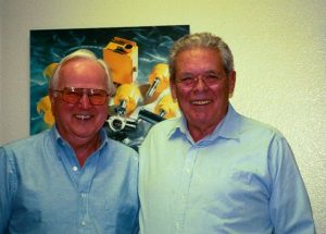
Photo by Jesse Yoder
Jesse Yoder, president of Flow Research, interviewed Bob Deane and Mac McQueen in Febryary 2003 at FCI’s headquarters in San Marcos, California.
The first interview is with Mac McQueen, cofounder of Fluid Components Int’l. It covers from 1964 to 1981. The second interview is with Mac McQueen and Bob Deane and covers 1981 to 2003. FCI was acquired by DwyerOmega in November 2024 and is now a DwyerOmega brand.
FCI: The Early Years, as told by Co-Founder Mac McQueen
Questions (Q.) are by Jesse Yoder
The way this got started, I had worked for the Whitaker Company, and as often happens, people bring ideas to companies for possible exploitation. One of the first inventors of thermal flow switches came to us and presented his material to us. I recommended that we not pursue it at the Whitaker Company at that time, because of all the variables involved in the thermal properties of different fluids and gases, and it seemed not too good of a way to go, considering the conditions and atmosphere at Whitaker. So initially I recommended against doing thermal flow switches.
Photo by Jesse Yoder
As opposed to our more recent flowmeter, a few years later Bob Deane came to me and told me that there was a need for a flow switch in the oil industry – production department. I thought about if for a week or so, and got some ideas and had Bob come over and discussed those ideas with him. Together we came up with a method of demonstrating how this thing would work, using a candy thermometer, a stainless steel mixing bowl, and a soldiering iron heater. This humble combination of devices was used to demonstrate the operating principle used to determine oil well function and production. As noted above, the above flow switch activity greatly preceded our more recent thermal flowmeter activity.
Q. What year was this?
This was 1964. So initially we started out in this field doing flow switches as opposed to flowmeters. It wasn’t until 1981 that we got around to entering the flowmetering field, and then it was only in gases.
Among the ideas I was tossing around for solving the oil well problem was thermal because although I had first recommended against it, there were some things about this application – it was oil and water, or emulsion of oil and water, and sand, and really a hostile environment where they would occasionally get very high velocities of congealed oil and ice and sand and rust, and anything that would come up out of the ground. The application was in Bakersfield, and occasionally a snowstorm came through and virtually froze the field up, temporarily, at least. But the pump didn’t stop; they kept pumping away, and the whole production string was slowly filled largely with high-pressure gas. Then the sun would come out, and it wouldn’t melt the whole plug; it would just melt the part that was stuck to the pipe.
So here comes this plug of ice and sand and gravel and every imaginable thing, including cats and dogs and so forth, howling past the sense point at Mach One. It had a couple thousand psi gas pressure drive. Finally when the plug would purge itself and here would come this blast of gas out of this thing at a high mach number, carrying abrasive particles.
So the application required something that was very rugged, and yet very sensitive, because they wanted to sense two barrels a day of flowrate in a two inch pipe. You can barely see it move if you aren’t watching closely. So it was a challenging requirement we started out with.
Finally we created a fluidic amplifier, wherein an emitter, gate, and base were mounted in a flowing pipeline. This fluidic amplifier operated just like an electronic triode. Except, heated liquid was emitter instead of electrons..
Q. How did it work?
Three ¼ diameter X 1 ½ inch long horizontal steel thermal wells were mounted in the pipe directly across the flow in the two-inch pipe. One thermal well (the emitter) contained a low power (10 watt) heater. Vertically above, parallel to and separated from the heater (about a ¼ inch gap) was a second thermal well containing a temperature sensor. The third thermal well was mounted about ¾ inches away and upstream of the other thermal wells.
During flow, all the heat from the heater was carried away downstream and dissipated into the media. When the ordinary flow stopped, a warm convection current rose vertically from the heater “emitter” across the “gate” (the ¼ inch gap) and heated the “base” temperature sensor to a higher temperature than the upstream temperature sensor. The temperature difference was used to alarm a no-flow condition. Typically, stopped water in the gap would cause a 20F temperature difference; oil would cause a 40F difference, and gas would cause a 70 to 100F difference. Even the slight flowrate of four inches per minute through the gap or gate caused the temperature difference to drop to zero.
No matter what the media, be it: gas, liquid, oil, water emulsions, or solids, gels, and the like; if it stopped, the upper sensor would heat up as compared to the upstream sensor, either by convection heat transfer in ordinary fluid or differential conduction in gels, ice, or solids through the ¼ inch “gate” gap as compared to the ¾ inch gap thermally isolating the upstream sensor from the heater “emitter.” An alarm trip point of 10oF was used as the alarm point; any temperature difference above 10oF would trigger the alarm.
It worked! This thing also became a flowmeter in a way. It was really kind of interesting how it happened. The oil company that was exploiting this particular technology would bring the oils up to 30 wells into many collecting points. At the collecting points, they would have diverter valves that would either divert this flow into a collecting gauge tank, or divert it into a production pipe, in order to pay the people that owned the well property their rightful royalties. Once a month, they would tank-gauge the amount of oil they were getting out of that particular well. It was also part of the management of the field.
Using this method, they could gauge the amount of volume being produced by each well by the gauge tank. They related that to the number of on /off times – how long it was staying on and how long it was staying off during the 24 hour period. They had 3000 wells in this field, and had a huge database. By scanning each well once every six minutes to see if it was on or off, and putting that information into the computer memory, and comparing that data with the periodic on-off periods during well gauging, they were able to tell within one percent how much oil was being produced that day. This was done by recording the on/off history vs. the gauging of that well. They were able to get a relationship between the on/off time of all the wells in the field and the amount of oil that was being produced.
Q. Does this give you the speed of the fluid?
No. All it did was say whether it was on or off as defined by the two barrel a day flowrate trip point. If the switch said it was on ten percent of the time, they knew that well was producing ten barrels a day because they periodically gauged it and the computer knew the relationship. So they related the “on” time of our switches to the amount of oil being produced in that well. Every month they’d get an update on on/off time and how much oil this well was producing. So by looking at the on/off times of all 3000 wells and the gauging data, they were able to statistically determine within one percent how much oil the field was producing. And they had geared up to 100,000 barrels per day. That was in Bakersfield, California.
Then they began to get some discrepancies between what was being produced and what was being shipped. And it wasn’t one percent; it was getting to be two percent or more, which is a significant amount of oil. And by one means or another, they found out that it was being stolen. They used our instruments to determine the rate at which they should be shipping. They had an additional metering instrument on the field to gauge the amount of oil that was actually going on the shipping pipeline. These two were diverging. And they found that the difference was being stolen.
Q. Was that Saddam Hussein who was stealing it?
[Laughter] No. It was some of the guys who were working in the field. I’ve been told that a lot of oil enters the industry through theft.
So that was our first entry into the field. We’re working in the kitchen, my partner’s dining room, and his garage. We are financing this out of our hip pockets. My partner was a manufacturer’s rep, so he was able to do some sales work on it and other things. I was the engineer and we’d work weekends and nights. Finally we got things going. At about that time, the Bakersfield-based oil company wanted to buy 3000 of these things. They knew we were just working in the garage, and weren’t capable of producing that number. So they asked us to license this to someone who would be more capable of producing that number. So we licensed the Whitaker Company on the technology in 1966. That didn’t work very well, so we got eventually got the license back. This also verified my earlier response that the ethics and work environment at Whitaker would not be conducive to a successful license. Oh well, another error!
We got the license back in 1970. Bob Deane, my partner, started up again in his garage. At this time, I was the consulting engineer. I had left the Whitaker Company’s employment back in 1964. I consulted with Whitaker and a lot of other companies while we were trying to get this going. We ultimately retrofitted all the 3000 Bakersfield instruments because Whitaker didn’t do a good job on it. We also sold another 3000 or 4000 for additional wells in the same field, with sales commencing in about 1973.
In this instance, thermal offered so many benefits, in terms of the mechanization that I had reversed my earlier opinion and we developed thermal instruments. It didn’t matter if it was oil or water or gas or steam or solids. Whatever was there, the instrument was able to tell whatever was there if it was moving or stopped. This is all the user wanted to know for oil production. If the product didn’t move for a long time, they sent a crew out to see what was wrong.
Oil wells are temperamental things. They’ll produce, then quit, produce again, and may stop for long periods of time. They’re not all consistent. One well right next to the other one can be totally different from the others. They have to watch them constantly to see what the trends are and in this case only automated “watch” was economical.
We went along making switches until 1981. At the same time, Kurz was developing flow transmitters for gas products. We concluded that we had the basis for doing transmitters if we put more sophisticated electronics on it. So that’s what we did. There may have been some dismay on the part of people in the industry doing transmitters that we had not only exploited the switch market, but now were coming onto their turf.
We went in anyway and we developed our earliest gas flow transmitter. About that time we moved out of Canoga Park in the San Fernando Valley and came down to San Marcos. We had in the meantime gotten involved in the nuclear industry, even though it was collapsing due to the accident at Three Mile Island. So although the industry was collapsing, we got into it with a new technology that had its own growth curve. So despite the downturn of the industry, we were on a growth curve that overcame the downturn.
Then we got into gauging, using the thermal technique of gauging tanks. First we discovered that the flow switch if you turn it upside down was a perfectly good liquid level indicator. So we began to make liquid level switches. It was so sensitive that it could tell the difference between oil and water, or sand and water, so we were able to interface between slurries and clear liquids, different non-miscible liquids, or liquids and gases.
Later, we invented long continuous heaters and RTDs, and were able to gauge the amount of fluid in a tank, as opposed to our initial effort of point interface sensing. After we did the fluidic amplifier, in order to get higher flowrate sensitivity, we changed the heat transfer method from convection to conduction. We did that by bringing the heater into direct fused metallic contact with the heated sensor. So now we were getting heat from the heater into this RTD by conduction, no “GAP” for convective heat transfer. The third separate thermal well was still operating as a reference temperature sensor. Now we could go to higher flowrates because it took a lot of flow across the thermally bonded heater/sensor array to cool the thing enough to be sensitive to flow. This became our first high flowrate sensor.
Q. You put the heater together with the sensor?
Yes, we fused the thermal wells together and eliminated the “GAP” and its free convection heat transfer path that existed in the absence of crossflow through the gap caused by normal media flow in the pipe. We fused them together so we had a conduction heat transfer path between them.
Q. What’s the difference between conduction and convection?
Convection would be like the following example. Suppose you have a burning cigarette in a still room. Smoke rises vertically several inches off the hot ember. That’s a convection flow. If you put your finger in there, you’d burn yourself even though you weren’t in touch with the hot ember, because you’re transferring heat from the hot ember to your finger through a smoky hot convection current. It’s thermally driven convection. If you put your finger on the burning ember, that burn would be caused by conduction.
If you put your heater in direct contact with the heated element, now you have conduction. That’s different from convection. There’s one other method of heat transfer, and that’s “radiant.” That’s how we get our heat from the sun – through radiation. It is not a heat transfer means currently used by use, but you can never tell when it might be used.
Once we fused the two together, we turned the thing upside down and we would still get conduction from the heater to the sensor. When the liquid came up and touched the heated sensor, it would cool it. We could tell when it got into the liquid. We were then able to make this flow switch into a liquid level sensor; the heater now above the heated sensor still heated the sensor by conduction through the “fused” junction of the two thermal walls.
Q. Did you have to put it at one location?
Yes, that would be what we called a point sensor. It would be like a float switch. You put it at one point and when the level is up to that point, it would float and close the contact. We had no moving parts, so there were a lot of people who liked that. Plus we were able to tell what fluids we were in because the heat transfer qualities were so different from fluid to fluid. Interestingly, because of many improvements, we are now able to offer this device as both a flow sensor or liquid level sensor and as a loop-powered sensor.
If you had an oil and water separator, for example, you could look at this instrument and tell if you were in oil or water. So we could do an interface sensor. Or if you were in water and you were transporting sand with that water, if the sand built up to a given level, we could tell if we were in sandy water or clear water. The sand would interfere with the heat transfer. It’s just like when you put your foot in the sand at the beach. Your ankle is still cool and your feet get warm. So we did interface sensing this way.
Later on we discovered that we could even point this downward and get extremely sensitive with a thimble full of water. If we were in a nuclear power plant and we wanted to know if there was leakage someplace, without putting any kind of a sump in or liquid gathering device, we could mount this just off the floor. If the slightest bit of water gathered underneath and carried the heat away, we could tell if it got even slightly wet. We also used those in water treatment plants where they had sludge, for example; where they had an interface between water and sludge in some of these separation systems. We could tell if we were in clear water or sludge.
We did some work in the juice industry where they wanted to know if they had pulp or clear orange juice. We could tell, because of the change in heat transfer.
Q. Would you have to try it out on different fluids?
Yes, we would have to try it out here to advise the people. First we would find out what media they were in and we duplicated it here. Or, we told them how to set it in the field, and they would cause the problem to occur. Then they could see the difference with a voltmeter as the media changed. Then they would set the trip point on the switch according to what the field results were.
The foregoing is basically the early company history prior to our moving to San Marcos in 1981. Thereafter the history resembles the old movie serial “The Perils of Pauline” more than the rational business that it currently is following my retirement.
FCI: The Later Years, as told by Co-Founders Mac McQueen and Bob Deane
This part of the interview picks up the story in 1981 and brings it up to
the time of the interview, first with Mac McQuen (MM) and then with Bob Dean (Bob). Questions (JY) are by Jesse Yoder of Flow Research.
FCI and Sierra Instruments
JY: When did Sierra Instruments get started?
MM: I don’t know when they started. They would probably claim that they pioneered this thing for flowmetering, “Where as we were pioneering it, I think earlier than them,” for flow switching and later put some sophisticated electronics on and were able to go into flowmetering. Now there was, “a cultural difference” that’s where we started. We started out in the oil patch so everything we made was like anti-tank weapons. Our stuff was much more robust than their equipment was. They had developed stuff that was quite delicate.
JY: And research?
MM: They were in gases, basically, and there was nothing like the hostility from the oil patch they grew up in, so they came to the market with a very delicate but fast acting flowmetering instrument.
The Origins of Thermal Flowmeters in Hot Wire Anemometers
JY: I heard that thermal flowmeters were developed out of hot wire anemometer switches and were very fragile.
MM: They were much more robust than hot wire anemometers because they had the steel jacket around their RTD’s, but the steel jacket they put on their stuff was much more fragile than the ones we were using. So we kind of came at it from different angles. We originally made flow switches for crude oil production and they were flowmetering gases in a mild environment. Now, since that time we’ve gone through continuous improvement of the device and we finally remodeled the switch in 1993 and made it much more accurate than it had been and probably better than any other switch on the market up to that point, because of its accuracy and wide flow range capability.
Many others have wrongly assumed our performance, but we’ve tested their switches and found them inaccurate and of limited range. Concurrently, with all of this, we are also developing the flowmetering, which led us into measuring the flow out of a smokestack and large diameter pipe systems.
Thermal Flowmeters in 1981
JY: Now is that gases?
MM: When we started in 1981 making flowmeters we had just the single point out in the stream where we had a thermal dispersion instrument but it was a heater fused to an RTD and a reference RTD in the system. We measured the cooling effect of the forced convection over the heated sensor by the flow in the pipe. In other words, you go to 100 feet a second in air-flow and you would be able to measure the cooling effect of 100 feet a second of gas as opposed to say 95 feet or some other lower value. It was sensitive enough that we could tell what the velocity of air in the pipe was provided we know the media and temperature.
JY: And that was based on the change of temperature?
MM: It was based on the change of temperature. If you have a heated element and you put it in a moving stream of fluid it is going to get cool. The faster the stream moves the cooler it gets until it reaches the stream temperature.
JY: Unless it’s hot fluids?
MM: Even if it is hot fluids. Remember we have a reference sensor in there too. We know what the fluid temperature is at all times and cooling is the difference between the heated sensor and the media. So, if you know what the temperature is and you know if it is moving it is going to cool the heated sensor depending on the fluid properties and the velocity of fluid. The faster the fluid is moving the more cooling you get right. So at no flow you might have 100-degree temperature difference between these two.
At no flow you have no forced convection cooling. Now as the flow starts coming up you get additional cooling from the forced convection of the fluid over the heated sensor. How Sierra’s and Kurz’s Flowmeters Differ from FCI’s All thermal devices work on that idea that you get greater cooling at higher velocities.
Now Sierra and Kurz have an electronic system that operates different from ours. What they do is they maintain a constant temperature between the heated and the unheated sensor and the higher the flowrate the more power they have to put in the heater to maintain that constant temperature. We put a fixed amount of heat in and say, okay we’re going to measure the amount of cooling you’ll get until it cools it all the way down to no difference. There are different electronic schemes, but they are all basically working on the same idea. You are getting additional cooling as the fluid moves faster.
JY: You must have some kind of a feedback system to maintain the system?
MM: Yes they have a kind of a feedback loop in their system; we don’t. They have an electronic servo-mechanism that maintains a constant temperature. Each one of the methods have their own peculiarities. We both came at the problem from different cultural positions and different electronic means of operation. We are now to the point where we are offering a liquid flow transmitter. Up until now everybody has been just gas flow. Gas flow is easier than liquid flow.
Gas vs. Liquid Thermal Flowmeters
JY: Because of the higher speed…
MM: Right. It takes is a lot more gas flow to cause the same amount of cooling as a small amount of liquid. So trying to get some range into your instrument in liquid is very difficult.
JY: I can see that.
MM: We have been able to come out with a liquid flow transmitter that will sense up to 15 ft. a second in water with about 1% to 2% accuracy.
JY: I just finished a study of thermal flowmeters for my all-technology study. I was amazed how it’s almost totally gas; it’s like 98.5% gas or something; very little liquid. There are about 4 or 5 companies that have it. Some liquid in thermal, but it’s very minimal. I always thought it was more like 20%.
Aerospace Applications for FCI’s Thermal Flowmeters
MM: The reason why there have been view people in it is that it’s very difficult to do. Because the flowrates they’re interested in liquids for commercial applications are up to 15 ft. a second. Aerospace is about 100 ft. per second or even higher. The reason is that aerospace is willing to pay pumping losses in small pipes in order to achieve weight savings. A small pipe weighs less, but it takes more energy to pump the same amount of fluid through it because it’s going it a lot faster. So in aerospace, because they want to save weight, they’re willing to spend the energy to pump the fluid. An airplane is very energy intensive; it has a lot of power in it.
JY: You’re talking about onboard systems.
MM: A jet engine pumps fuel about 150 ft. a second. That’s much higher than you would find in commercial devices. The reason that there are few in commercial flowmetering and thermal dispersion is simply that the liquid cools the instrument so quickly that you don’t get much range out of it. We have recently come upon a scheme whereby, we can suppress the amount of cooling that you get, and we can now go up to 15 feet a second in water with about 2% accuracy or even better. Right now we are just beginning to penetrate that field, but it looks like 2% accuracy is very attainable for us.
JY: And this is the new product you have that is already out there?
MM: Yes! That’s what I’ve been talking to these guys about. Our first application is already with Boeing in an airplane and many other and many other military and commercial applications are in service. We’ve done a lot of work in this area in research and development so we know where we are going with it, but this is the first time that we’ve actually taken a contract to develop a thermal dispersion liquid flowmeter. We’re very confident that we can do it. In fact I’m absolutely sure that we can do it. The agreement with the Boeing incidentally is that if we failed doing it, we will pay to have somebody else do.
JY: Oh I’m sure you will be able to do it in that case! Go to Kurz and have them do it.
MM: I don’t think that’s going to happen. Nom they couldn’t go to Kurz or Sierra because neither one of them know how to do this thing in liquid, but we have come up with a method for doing it in liquid. We are off and running on it and have excellent patent protection as well. I don’t want to get into all kinds of technical details but it operates on a slightly different thermal heat transfer principle, than the ordinary flowmeters that we find for gases.
JY: Is that fundamentally different?
MM: It’s a difference in structure. Structural differences have allowed us to go to comparatively high velocities in liquids. In gases we could easily go to 2,500 standard feet per second in gases, which is way beyond the present range of gas flow instruments. That’s kind of an abbreviated update on where we are. We pride ourselves in being the only flow switch manufacturer at least in this country that we know about who would guarantee their instrument on an accuracy basis. It is because of that accuracy that we have woven in to our flow switch business that we are able to transfer into the transmitter business very easily.
RTDs and Other Components
JY: Now do you make your own RTD’s?
MM: No, we buy them. We use different types of RTD’s; some wirewound and some chip. Sometimes we have selfheated and sometimes we have separate heaters.
JY: Have you thought about making your own?
MM: We found there was no need of it; we found that we can get very good RTD’s at low cost.
JY: Do you pretty much make the other components?
MM: We just buy the RTD’s. We don’t make our own microchip electronic components either. We’re not going to manufacture anything we can buy.
Note: This concludes the interview with Mac McQueen.
Interview with Bob Deane
Bob Deane: So in 1981 we built this building and moved down here. We brought twenty-two employees down here. It was just the two of us. We built this big building and we only had twenty-two employees to put in it.
JY: In 1981?
Bob: In 1981.
JY: You grew so fast.
Bob: It’s a good product. By then we had taken the product into sanitary world. We understood the 3D requirement for that world, we were selling some real extensive nuclear stuff at the time. Not right in the reactor but on the side of the reactor in the containment building. It qualified so we had a qualification going. We didn’t get into Aerospace until we got down here though. We were doing all kinds of industrial selling, all kinds of oil sales. The funny thing is the oil patch never took off as our prime area of sales.
JY: Even though that was where you started.
Bob: That was where we started. It was in the refinery petrochemical plant where the need for our product was the greatest. When we got down here we moved here in 1981 with 22 employees in this building. We took a piece of it and tried to rent the rest of it.
JY: So this building already existed.
Bob: No, no we built it. We gambled. Not only gambling the company, but we built the building. I have some funny stories. My wife wrote all the checks in the early days, passed out the money, knew all the employees. Up there in Conoga Park the rent was twenty five hundred dollars a month for the two buildings.
JY: For the two buildings.
Bob: Both buildings for $2500 a month. We moved down here and we moved in and they got the construction loan finalized and then we started making regular payments on this building. The payments started at $25,000 a month. She wrote that check and she just had a heart attack. Her hand was shaking. She never wrote a check that big in her life. I have to write one like this again next month! I said were going to get the business in. So we immediately started staffing up here.
JY: That was equity, though; that wasn’t rent.
Bob: Yes. But the building was owned by a group of four people; Mac and I were two of them. Fluid Components was the master tenant of the building. So they needed to make the payments. It’s the kind of gamble you take, along with trying to constantly improve the product line. That’s what we’ve always done.
JY: You still seem to be doing that.
Bob: Oh, we could spend the rest of our life improving the product line. We’ve been doing this for 30 plus years, and we know more about it than anybody. There’s still need to polish that apple.
JY: I see now that you’re reselling Coriolis meters from Danfoss.
Bob: Since Mac and I left, Dan’s a little more open to increasing the sales [Dan McQueen president of FCI]. In the mass area, we’re not sure where we’ll cap out at. When somebody new comes along, it pushes it down a little. Many people have come by over the years and wanted to buy the company. But the fit was the Coriolis meter; we also brought in the Vortab flow conditioner as a companion item.